| Brief Description | |
|---|---|
|
Files:
\Examples\Acquisition\DataForwarding\iF2D100\DFExample_Host.vad
|
![]() |
|
Default Platform: iF2D100 |
|
|
Short Description Data forwarding implementation on imaFlex 2 Dual 100 platform is presented. |
|
A typical data forwarding environment with daisy-chained frame grabbers looks as follows:
The first device on the left acts as the host (master) for the following connected clients (slaves). Data received by the host device, for example from a camera, is forwarded to the clients. Depending on the use case, a client either forwards the complete original stream data or only a part of it. This behavior continues from device to device until the end of the daisy chain.
The data forwarding capabilities of the Basler imaFlex 2 Dual 100 allow not only the forwarding of image data, but also forwarding of metadata, for example to remotely control client devices. The following section describes a basic example that demonstrates both aspects.
The example applets are for use with the corresponding data forwarding SDK example
applications DFMaster and DFSlave. Therefore,
no manual loading of the applets, for example via microDisplay X, is required. The SDK
example applications automatically load the applets, and all user interaction is done
exclusively through the host (master) application.
For information on using the frame grabber SDK scripts, refer to the corresponding
script documentation located under
examples\Acquisition\DataForwarding\SDK in the VisualApplets
installation directory.
The example applets demonstrate data forwarding with two aspects in mind:
-
Transfer (generated test) image data from the host to its subsequent clients.
-
Remotely control and monitor the clients.
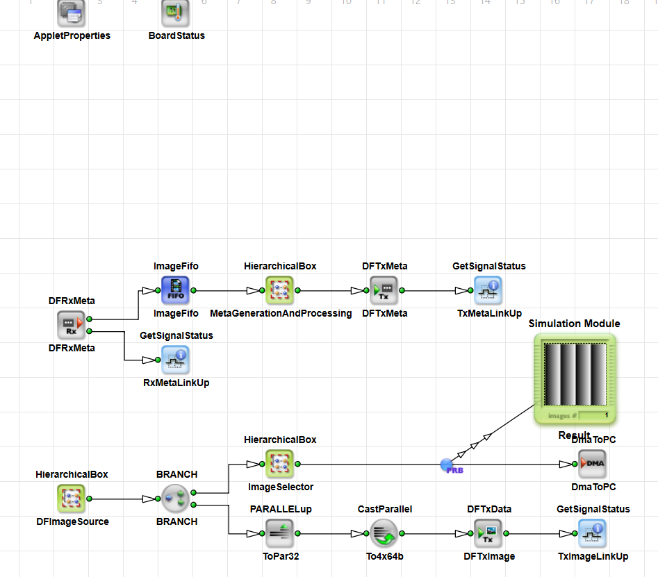
Image data transfer is straightforward and easy to implement. Each example applet shows this in its image path.
Remote control and monitoring require more effort, because you can't dynamically change applet parameters by using data from the VisualAopplet links such as incoming control commands. You can address this limitation by using the VisualApplets event system. The remote control metadata path demonstrates this approach.
Although the applet design shows the two paths separately, both paths share the same fiber resource for a single device pair. Image data is transmitted over all four fiber lanes numbered zero through three, while remote control data/metadata uses lane zero of the same fiber module.
In other words, the 2×4 lanes of a fiber module connect two devices in a bi-directional manner for both image and metadata. The corresponding data forwarding operators DFTxImage, DFTxMeta, DFRxImage, and DFRxMeta manage this internally.
The table below summarizes the data forwarding connections implemented in the example.
| Fiber Port | Host | Mid-Clients | End-Client |
|---|---|---|---|
| port0 | reserved (for example camera) | prev | prev |
| port1 | next | next | — |
Table 17. Data Forwarding Connections (Fiber Ports)
For detailed documentation on the processing structure of the example design files,
see the comment boxes in the corresponding *.vad designs.
The idea behind using the VisualApplets event system for remote control is that the Framegrabber SDK API provides routines to access operator and applet parameters. With the VisualApplets event system, it is possible to send events with payload data from the applet to the host PC, and an event-monitoring SDK application can react on the payload.
With that in mind, the remote control signal flow is as follows:
-
The host applet sends a command to the client.
-
In the client applet, each received control command triggers an event (with payload).
-
The event is captured by the frame grabber OS driver.
-
An event-monitoring SDK application executes an SDK routine according to the interpretation of the event payload.
The data forwarding example uses a user-defined communication protocol. In this scope, a command transaction is called a message. The structure of a message is shown below:
| Bit Index | Description | Size (bits) |
|---|---|---|
| [55] | Read-not-write flag | 1 |
| [54:48] | Client (slave) device address | 7 |
| [47:32] | Software-accessible register address | 16 |
| [31:0] | Software-accessible register data | 32 |
Table 18. Message Bit Layout
A message is 56 bits in total, which corresponds to the size of one data word of the DFTxMeta and DFRxMeta operators.
A message trigger initiates a message. The SDK host application configures both the message content and the trigger.
In general, data that travels on a VisualApplets link can be handled in different ways. For the data forwarding example, the following two handling methods are relevant:
-
The system directly uses the command data bits. For example, it converts a dedicated bit into a
VALT_SIGNALand routes it to the GPO bank. -
The system triggers a VisualApplets event and can include payload data extracted from the remote command.
The first handling method represents a hardware command. The system uses the message bits as signal sources to trigger dedicated actions. The second handling method represents a software command, because the driver software handles the event sent to the host PC. The data forwarding example implements both command types, with a focus on software commands.


Prev

